Antenna Test & Calibration
We promote experience.knowledge.excellence.
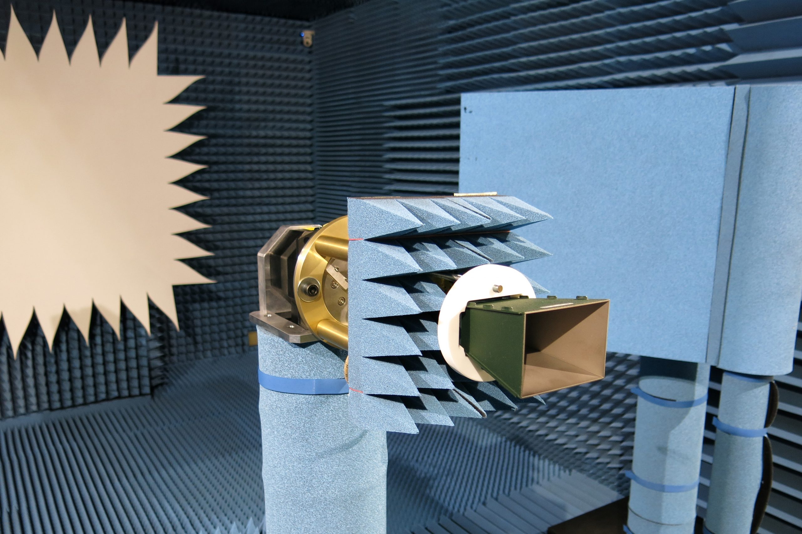
Antenna Systems Solutions offers a comprehensive antenna testing service tailored for your needs. All our measurements are carried in out in a type approved accredited anechoic chamber in Madrid (Spain) according to the ISO17025* standard.
Spherical Near Field
Planar Near Field
Cylindrical Near Field
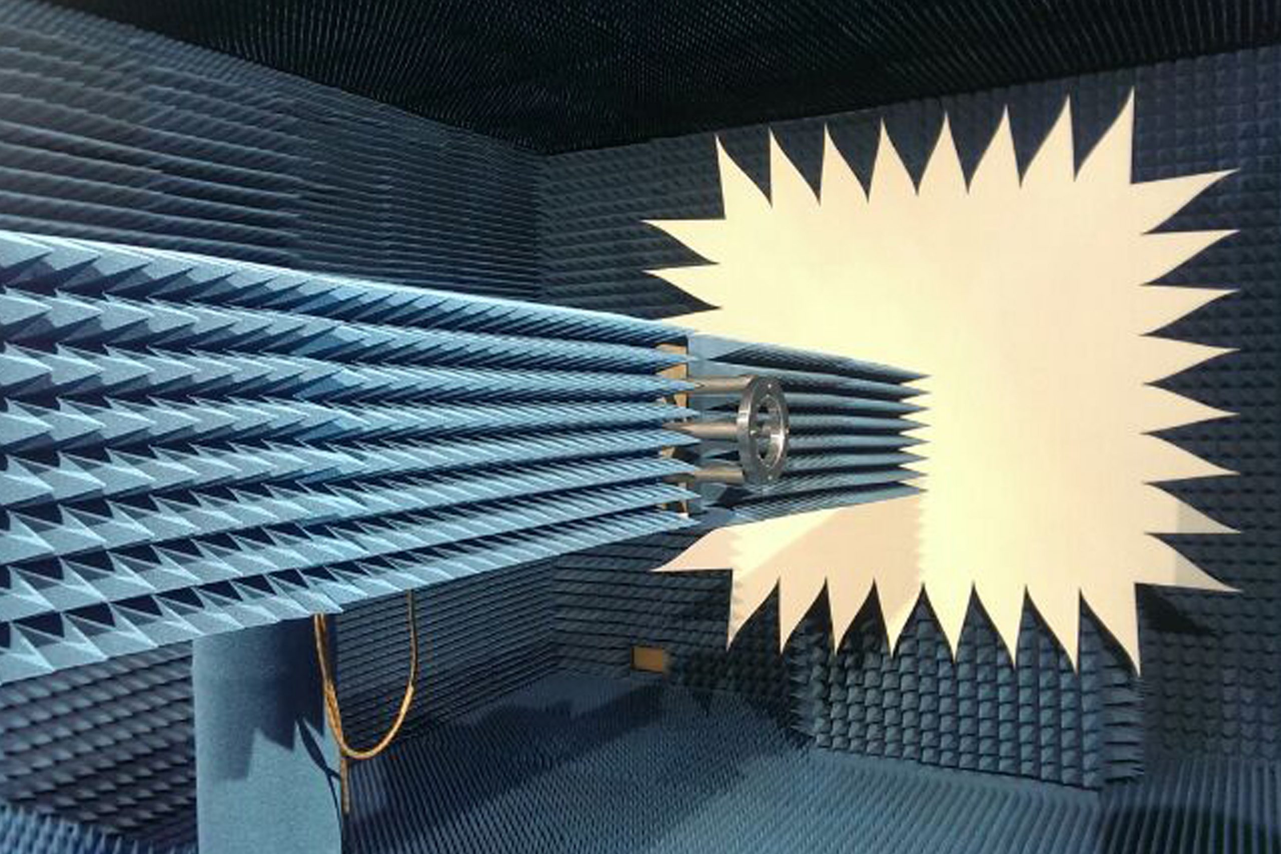
Compact Range
Please contact the sales office for a quotation and availability
Highlights & Facilities
The antenna test ranges consists of three anechoic radiofrequency chambers:
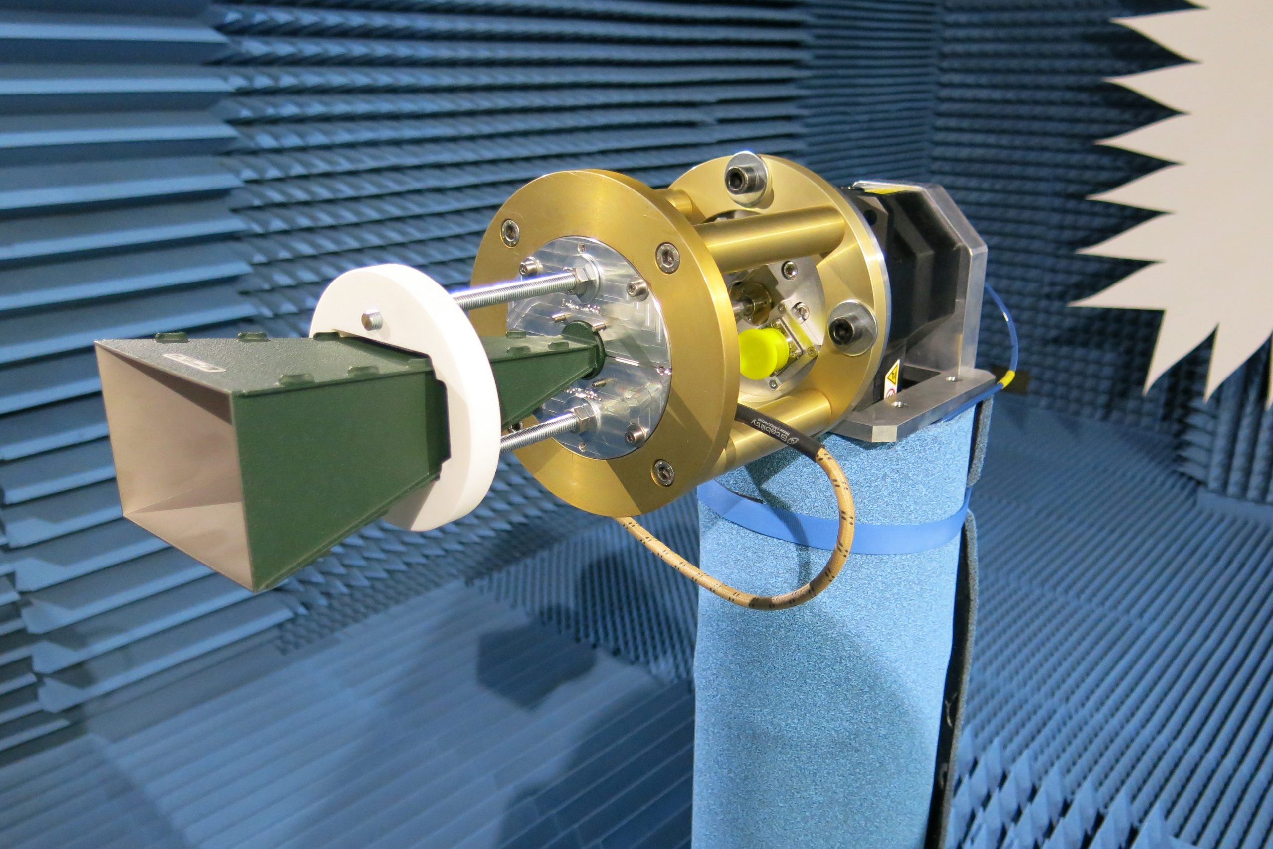
Spherical near field antenna measurements
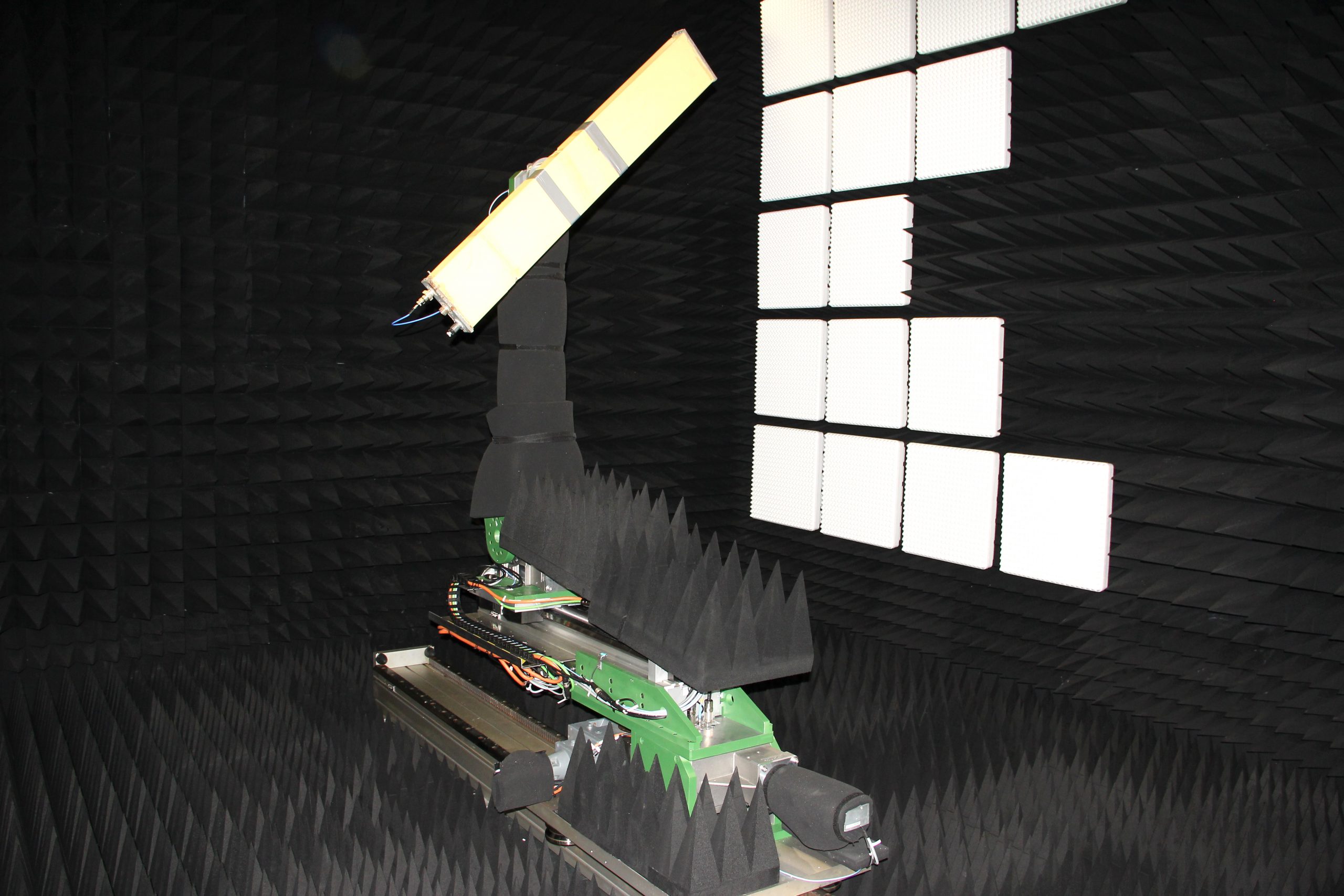
Compact range and a planar-cylindrical-spherical near field system in order to measure large antennas and RCS
The two chambers share two complete radiofrequency and control systems, placed in two contiguous rooms. The anechoic chambers are equipped with air conditioning systems, with filters class 10000 (clean area), in order to measure on board satellite antennas.
From 0.8 to 60 GHz
Dimensions up to 2.5 meters (Satellite antennas, earth stations, cellular telephony base stations, active & passive arrays)
Radar Cross Section
Measurement of Radar Cross Section of materials from 6 to 40 GHz
Radomes
Measurement of radomes and similar structures for antennas from 0.8 to 40 GHz
